
I originally posted this at http://blogs.sun.com/brendan/entry/l2arc_screenshots.
Back before the Fishworks project went public, I posted an entry to explain how the ZFS L2ARC worked (Level 2 Cache): which is a flash memory based cache currently intended for random read workloads. I was itching to show screenshots from Analytics, which I'm now able to do. From these screenshots, I'll be able to describe in detail how the L2ARC performs.
Summary
There are a couple of screenshots that really tell the story. This is on a Sun Storage 7410 with the following specs:
- 128 Gbytes of DRAM
- 6 x 100 Gbyte "Readzillas" (read optimized SSDs) as the L2ARC
- 6 x JBODs (disk trays), for a total of 140 disks configured with mirroring
As a workload, I'm using 10 clients (described previously), 2 random read threads per client with an 8 Kbyte I/O size, and a 500 Gbyte total working set mounted over NFS. This 500 Gbyte working set represents your frequently accessed data ("hot" data) that you'd like to be cached. This doesn't represent the total file or database size, which may be dozens of Tbytes. From Analytics on the 7410:
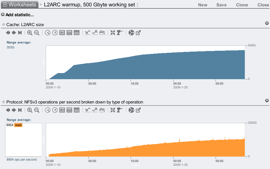
The top graph shows the L2ARC population level, and the bottom shows NFS operations/sec. As the L2ARC warms up, delivered performance in terms of read ops/sec increases, as data is returned from the SSD based L2ARC rather than slower disks. The L2ARC has increased the IOPS by over 5x.
5x IOPS! That's the difference 6 of our current SSDs makes when added to: 140 disks configured with mirroring plus 128 Gbytes of warm DRAM cache – meaning this system was already tuned and configured to serve this workload as fast as possible, yet the L2ARC has no problem magnifying performance further. If I had used fewer disks, or configured them with RAID-Z (RAID-5), or used less DRAM, this improvement ratio would be much higher (demonstrated later.) But I'm not showing this in the summary because this isn't about IOPS – this is about latency:
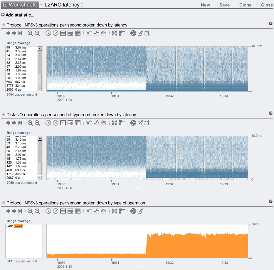
Here I've toggled a switch to enable and disable the L2ARC. The left half of these graphs shows the L2ARC disabled, which is the performance from disks plus the DRAM cache. The right half shows the L2ARC enabled, so that its effect can be compared. Heat maps have been used to graph latency, which is the time to service that I/O. Lower is faster, and the darker colors represent more I/Os occurred at that time (x-axis) at that latency (y-axis). Lower dark colors is better: it means I/Os are completing quickly.
These maps show I/O latency plummet when the L2ARC is enabled, delivering I/O faster than disk was able to. Latency at both the NFS level and disk level can be seen, which is often helpful for locating where latency originates; here it simply shows that the faster SSD performance is being delivered to NFS. There are still some I/Os occurring slowly when the L2ARC is enabled (lighter colors in the top right), as the L2ARC is only 96% warm at this point, so 4% of the requested I/Os are still being serviced from disk. If I let the L2ARC warmup further, the top right will continue to fade.
There is one subtle difference between the heat maps. Can you spot it? There is a dark stripe of frequent and fast I/O at the bottom of the NFS latency map, which doesn't appear in the disk map. These are read requests that hit the DRAM cache, and return from there.
The bottom graph shows IOPS, which increased (over 5x) when the L2ARC was enabled as due to the faster I/O latency.
This is just one demonstration of the L2ARC. I've shown a good result, but this isn't the best latency or IOPS improvement possible.
Before: DRAM + disk
Lets look closer at the NFS latency before the L2ARC was enabled:
This shows the performance delivered by DRAM plus the 140 mirrored disks. The latency is mostly between 0 and 10 ms, which is to be expected for a random read workload on 7,200 RPM disks.
Zooming in:
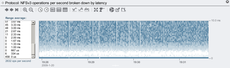
The vertical scale has now been zoomed to 10 ms. The dark line at the bottom is for hits from the DRAM cache, which is averaging about 460 hits/sec. Then there is a void until about 2 ms, where these disks start to return random IOPS.
After: DRAM + L2ARC + disk
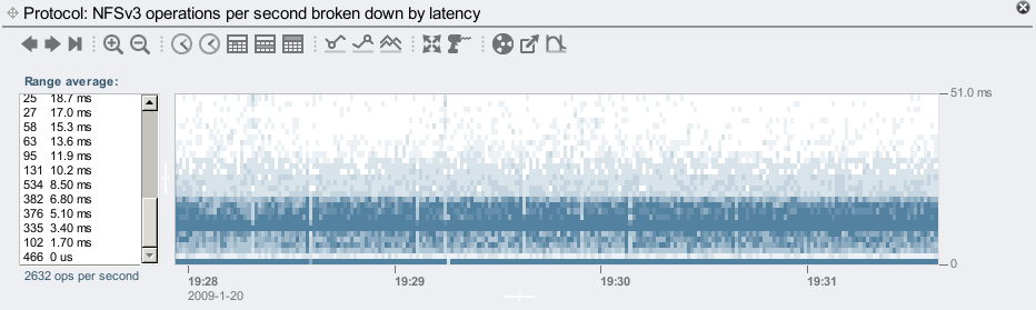
Now a closer look at the NFS latency with the L2ARC enabled, and warmed up:
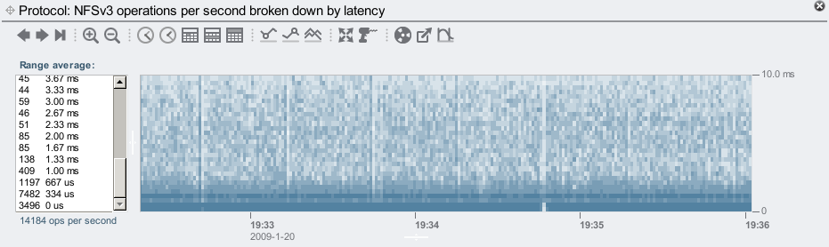
Here I've already zoomed to the 10 ms range, which covers most of the I/O. In fact, the left panel shows that most I/O took less than 1 ms.
Zooming in further:
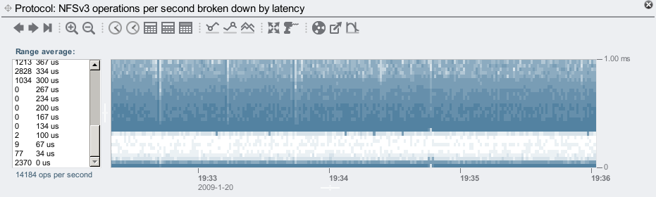
The L2ARC now begins returning data over NFS at 300 us, and as the previous graph showed, most I/O are returned by 1 ms, rather than 10 ms for disk.
The bottom line in the graph is DRAM cache hits, which is now about 2400 hits/sec: over 5x than without the L2ARC. This may sound strange at first (how can the L2ARC affect DRAM cache performance?), but it makes sense – the client applications aren't stalled waiting for slower disks, and can send more IOPS. More IOPS means more chance of hitting from the DRAM cache, and a higher hits/sec value. The hits/misses rate is actually the same, we are just making better use of the DRAM cache as the clients can request from it more frequently.
Hit Rate
We can see how the DRAM cache hits increases as the L2ARC warms up with the following screenshot. This shows hit statistics for the ARC (DRAM cache) and L2ARC (SSD cache):
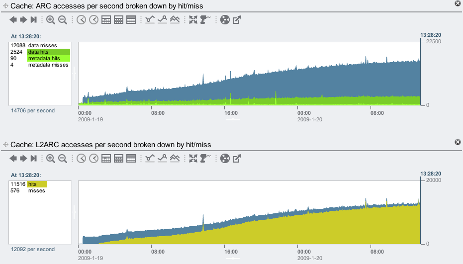
As the L2ARC warms up, its hit rate improves. The ARC also serves more hits as the clients are able to send more IOPS.
We may have assumed that hits improved in this way, however it is still a good idea to check such assumptions whenever possible. Analytics makes it easy to check different areas of the software stack, from NFS ops down to disk ops.
Disk ops
For a different look at L2ARC warmup, we can examine disk ops/sec by disk:
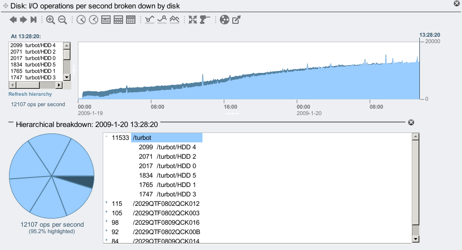
Rather than highlighting individual disks, I've used the Hierarchical breakdown to highlight the system itself ("/turbot") in pale blue. The system is the head node of the 7410, and has 6 L2ARC SSDs – visible as the 6 wedges in the pie chart. The JBODs are not highlighted here, and their ops/sec is shown in the default dark blue. The graph shows the disk ops to the JBODs decreases over time, and those to the L2ARC SSDs increases, as expected.
Warmup Time
A characteristic can be seen in these screenshots that I haven't mentioned yet: the L2ARC is usually slow to warmup. Since it is caching a random read workload, it only warms up as fast as that data can be randomly read from disk, and these workloads have very low throughput.
Zooming in to the start of the L2ARC warmup:
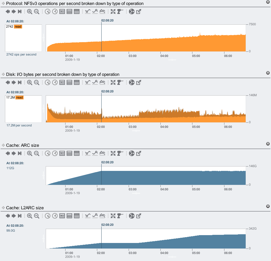
The point I've selected (02:08:20) is when the ARC (DRAM cache) has warmed up, shown in the 3rd graph, which took over 92 minutes! This isn't the L2ARC – this is just to warmup main memory. The reason is shown in the 2nd graph: the read throughput from the disks, which is populating DRAM, is less than 20 Mbytes/sec. This is due to the workload, we are doing around 2,700 x 8 Kbyte random reads/sec, some which are returning from the DRAM cache, which leaves a total throughput of less than 20 Mbytes/sec. The system has 128 Gbytes of DRAM, of which 112 Gbytes was used for the ARC. Warming up 112 Gbytes of DRAM at 20 Mbytes/sec should take 95 minutes, consistent with the real time it took. (The actual disk throughput is faster to begin with as it pulls in filesystem metadata, then slows down afterwards.)
If 112 Gbytes of DRAM takes 92 minutes to warmup, our 500 Gbytes of flash SSD based L2ARC should take at least 7 hours to warmup. In reality it takes longer. The top screenshot shows this took over a day to get warm. As the L2ARC warms up and serves requests, there are fewer requests to be served by disk, so that 20 Mbytes/sec of input decays.
The warmup isn't so much a problem because:
- While it may take a while to warmup (depending on workload and L2ARC capacity), unless you are rebooting your production servers every couple of days, you'll find you spend more time warm than cold. We are also working on a persistent L2ARC, so if a server does reboot it can begin warm, which will be available in a future update.
- The L2ARC does warmup half its capacity rather quickly, to give you an early performance boost. It's getting to 100% that takes a while. This is visible in the top screenshot – the two steps at the start raise the L2ARC size quickly.
If we were to warmup the L2ARC more aggressively, it can hurt overall system performance. The L2ARC has been designed to either help performance or do nothing, so you shouldn't have to worry if it may be causing a performance issue.
More IOPS
I mentioned earlier that the IOPS improvement would be higher with fewer disks or RAID-Z. To see what that looks like, I used the same system, clients and workload, but with 2 JBODs (48 disks) configured with RAID-Z2 (double parity) and wide stripes (46 disks wide.) The Sun Storage 7410 provides RAID-Z2 wide stripes as a configuration option to maximize capacity (and price/Gbyte), but it does warn you not to pick this for performance:
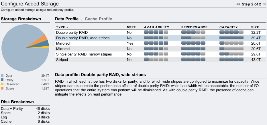
If you had a random I/O workload in mind, you wouldn't want to pick RAID-Z2 wide stripes as each I/O must read from every disk in the stripe, and random IOPS will suffer badly. Ideally you'd pick mirroring (and my first screenshot in this post demonstrated that.) You could try RAID-Z narrow stripes if their performance was sufficient.
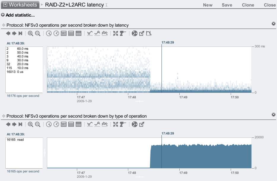
Here is the result: 2 JBODs with RAID-Z2 wide stripes, warming up 6 L2ARC cache SSDs:
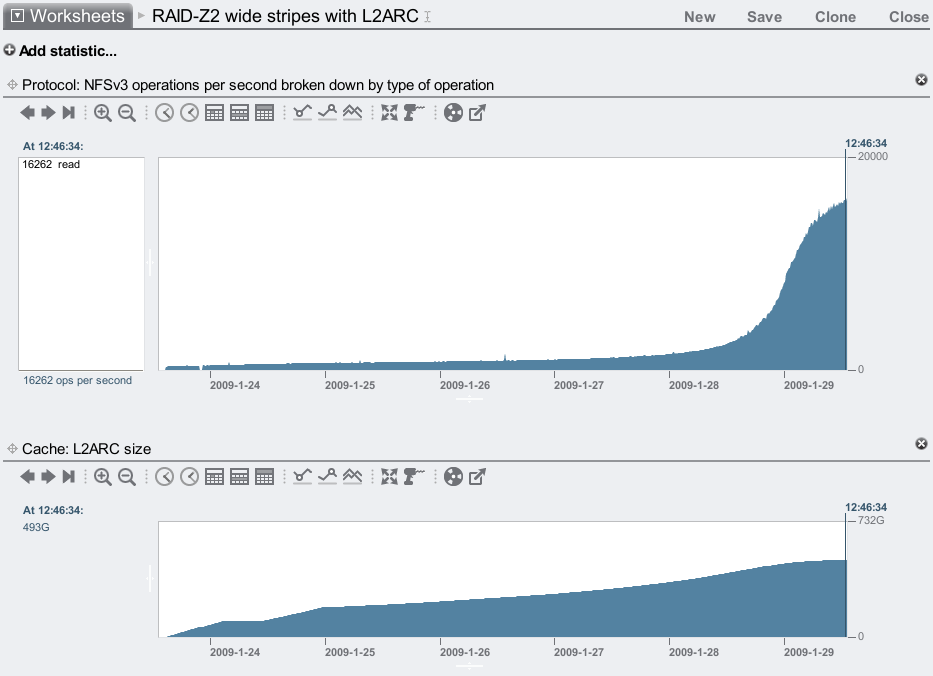
IOPS increased by 40x! ... While impressive, this is also unrealistic, as no one would pick RAID-Z2 wide stripes for a random I/O workload in the first place.
But wait...
Didn't I just fix the problem? The random read ops/sec reached the same rate as with the 6 x JBOD mirrored system, and yet I was now using 2 x JBODs of RAID-Z2 wide stripes. The L2ARC, once warm, has compensated for the reduced disk performance. So we get great performance, and great price/Gbyte.
So while this setup appeared completely unrealistic, it turns out it could make some sense in certain situations, particularly if price/Gbyte was the most important factor to consider.
There are some things to note:
- The filesystem reads began so low in this example (because of RAID-Z2 wide stripes), that disk input began at 2 Mbytes/sec then decayed. This meant that 500 Gbytes of L2ARC took 6 days to warmup.
- Since disk IOPS were so painfully slow, any significant percentage of them stalled the clients to a crawl. The real boost only happened when the L2ARC was more than 90% warm, so that these slow disk IOPS were marginalized – the dramatic profile at the end of the NFS ops/sec graph. This means you really want your working set to fit into available L2ARC; if it was only 10% bigger, then the improvement may drop from 40x to 10x; and for 20% bigger: 5x. The penalty when using mirroring isn't so steep.
- While the working set may fit entirely in the L2ARC, any outlier requests that go to disk will be very slow. For time sensitive applications, you'd still pick mirroring.
This tactic isn't really different for DRAM. Ff your working set fit into the DRAM cache (and this 7410 has 128 Gbytes of DRAM), then you could also use slower disk configurations, as long as warmup time and misses were acceptable. And the IOPS from DRAM gets much higher.
The before/after latency maps for this test were:
By zooming in to the before and after sections (as before), I could see that most of the I/O were taking between 20 and 90 ms without the L2ARC, and then mostly less than 1 ms with the L2ARC enabled.
Adding more disks
You don't need the L2ARC to get more IOPS, as you can just add more disks. Lets say you could choose between a system with L2ARC SSDs delivering 10,000 IOPS for your workload, or a system with many more disks that also delivers 10,000 IOPS. Which is better?
The L2ARC based system can reduce cost, power and space (part of Adam's HSP strategy with flash memory). The latency of IOPS delivered by the L2ARC is also favorable, as it delivers 10,000 fast IOPS (flash SSD based) vs 10,000 slow IOPS (rotating disk based). Latency is more important than IOPS.
Flash disks as primary storage
You could use flash based SSD disks for primary storage (and I'm sure SSD vendors would love you to), it's a matter of balancing price/performance and price/Gbyte. The L2ARC means you get the benefits of faster flash memory-based I/O, plus inexpensive high density storage from disks (I'm currently using 1 Tbyte 7,200 RPM disks). The disks themselves provide the redundancy: you don't need to mirror the L2ARC SSDs (and hence buy more), as any failed L2ARC request is passed down to the primary storage.
Other uses for the L2ARC
The L2ARC is great at extending the reach of caching in terms of size, but it may have other uses too (in terms of time). Consider the following example: you have a desktop or laptop with 2 Gbytes of DRAM, and an application goes haywire consuming all memory until it crashes. Now everything else you had running is slow, as their cached pages were kicked out of DRAM by the misbehaving app, and now must be read back in from disk. Sound familiar?
Now consider you had 2 Gbytes (or more) of L2ARC. Since the L2ARC copies what is in DRAM, it will copy the DRAM filesystem cache. When the misbehaving app kicks this out, the L2ARC still has a copy on fast media – again, they return quickly. Interesting! The L2ARC is serving as a backup of your DRAM cache.
This also applies to enterprise environments: what happens if you backup an entire filesystem on a production server? Not only can the additional I/O interfere with client performance, but the backup process can dump the hot DRAM cache as it streams through files – degrading performance much further. With the L2ARC, current and recent DRAM cache pages may be available on flash memory, reducing the performance loss during such perturbations. Here the limited L2ARC warmup rate is beneficial: hot data can be kicked out of DRAM quickly, but not the L2ARC.
Expectations
While the L2ARC can greatly improve performance, it's important to understand which workloads this is for, to help set realistic expectations. Here's a summary:
- The L2ARC benefits will be more visible to workloads with a high random read component. The L2ARC can help mixed random read/write workloads, however the higher the overall write ratio (specifically, write throughput) the more difficult it will be for the L2ARC to cache the working set, as it becomes a moving target.
- The L2ARC is currently suited for 8 Kbyte I/Os. By default, ZFS picks a record size (also called "database size") of 128 Kbytes, so if you are using the L2ARC, you want to set that down to 8 Kbytes before creating your files. You may already be doing this to improve your random read performance from disk. 128 Kbytes is best for streaming workloads instead (or small files, where it shouldn't matter.) You could try 4 or 16 Kbytes, if it matched the application I/O size, but I wouldn't go further without testing. Higher will reduce the IOPS, smaller will eat more DRAM for metadata.
- The L2ARC can be slow to warmup (as is massive amounts of DRAM and a random read workload) as discussed earlier.
- Use multiple L2ARC SSD devices ("Readzillas") to improve performance, not just for the capacity, but for the concurrent I/O. This is just like adding disk spindles to improve IOPS – but without the spindles. Each Readzilla the 7410 currently uses delivers around 3100 x 8 Kbyte read ops/sec. If you use 6 of them, that's over 18,000 x 8 Kbyte read ops/sec, plus what you get from the DRAM cache.
- It costs some DRAM to reference the L2ARC, at a rate proportional to record size. For example, it currently takes about 15 Gbytes of DRAM to reference 600 Gbytes of L2ARC at an 8 Kbyte ZFS record size. If you use a 16 Kbyte record size, that cost would halve: 7.5 Gbytes. This means you shouldn't, for example, configure a system with only 8 Gbytes of DRAM, 600 Gbytes of L2ARC, and an 8 Kbyte record size – if you did, the L2ARC would never fully populate.
The L2ARC warmup up in the first example reached 477 Gbytes of cached content. The following screenshot shows how much ARC (DRAM) metadata was needed to reference both the ARC and L2ARC data contents (ARC headers + L2ARC headers), at an 8 Kbyte record size:
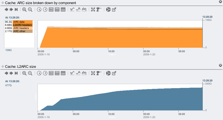
It reached 11.28 Gbytes of metadata. Metadata has always been needed for the DRAM cache: this is the in memory information to reference the data, plus locks and counters (for ZFS coders: mostly arc_buf_hdr_t). The L2ARC uses similar in-memory information to refer to its in-SSD content, only this time we are referencing up to 600 Gbytes of content rather than 128 Gbytes for DRAM alone (current maximums for the 7410).
Conclusion
The L2ARC can cache random read workloads on flash based SSD, reducing the I/O latency to sub-millisecond times. This fast response time from SSD is also consistent, unlike a mechanical disk with moving parts. By reducing I/O latency, IOPS may also improve, as the client applications can send more frequent requests. The examples here showed most I/O returned in sub-millisecond times with the L2ARC enabled, and 5x and 40x IOPS over just disk + DRAM.
The L2ARC does take a while to warmup, due to the nature of the workload it is intended to cache: random read I/O. It is preferable to set the filesystem record size to 8 Kbytes or so before using the L2ARC, and to also use multiple SSDs for concurrency. These examples all used 6 x 100 Gbyte SSDs, to entirely cache the working set.
While these screenshots are impressive, flash memory SSDs continue to get faster and have greater capacities. A year from now, I'd expect to see screenshots of even lower latency and even higher IOPS, for larger working sets. It's an exciting time to be working with flash memory.